Standardizing Radio Programming: A DIY USB-to-UART Adapter with RJ12
Whether you are a radio amateur (HAM) or a general electronics hobbyist, you almost certainly have a drawer full of USB-to-UART adapters. I am no exception — I have accumulated a couple of different ones over the years.
However, when I started working with amateur radios, I realized a convenient truth: most Chinese transceivers do not require any proprietary or special programming chips. Under the hood, they communicate via standard serial UART. All you really need to program them is a basic USB-to-UART bridge and the correct physical connections.
To simplify my workflow, I decided to design my own USB-to-UART adapter. While it is a relatively simple hardware project, it incorporates a few key design improvements that make it far more practical than standard off-the-shelf adapters.
The Core Concept: Why RJ12?
If you have used generic USB-to-UART boards, you know how annoying they can be. Every adapter has a slightly different pinout on its pin-headers. Before programming a radio, you always have to verify which pins are TX, RX, VCC, and GND, and make sure you don’t swap them. It is easy to make a mistake, and tracing individual jumper wires gets tedious.
The inspiration to solve this came from a Tag-Connect adapter I previously bought for an ST-Link programmer. It used a standard RJ12 connector, which I realized was incredibly handy for this kind of application.
I decided to make RJ12 my personal physical standard for serial programming. By placing a single RJ12 socket on the adapter board, I eliminated all loose jumper wires. Instead of checking the pinout every time, I defined a fixed pinout for the RJ12 socket on the adapter:
- VCC
- TX
- RX
- CTS
- RTS
- GND
With this setup, I only had to build a few custom cables once:
- For Baofeng-style radios: An RJ12 plug on one side, and the classic Kenwood 2 audio jacks (3.5mm and 2.5mm) on the other.
- For the Retevis B63S: An RJ12 plug on one side, and a USB-C connector on the other, routing the radio’s internal UART lines to the adapter.
Now, whenever I need to program a radio, I just grab the correct pre-made cable, plug it in, and start.
Hardware Design Features
Besides the RJ12 connector, I wanted to build a board that was robust, compact, and safe to use. Here are the main features of the design:
1. CH340E Transceiver
I chose the CH340E as the USB-to-UART bridge. It is a very compact MSOP10 chip that is highly reliable, cheap, widely supported by operating systems, and requires very few external passive components.
2. Dedicated USB Protection
Amateur radio environments are prone to static electricity (ESD) and high RF fields. To safeguard both the transceiver chip and the host computer’s USB port, I added a dedicated USBLC6-2SC6 ESD protection IC. This small chip suppresses high-voltage transients on the USB data lines.
3. Jumperless Voltage Selection
Most commercial adapters use a 3-pin header with a plastic jumper cap to select between 5V and 3.3V logic levels. These jumper caps are easy to lose and annoying to swap. I replaced it with a simple, low-profile slide switch to choose the logic level instantly.
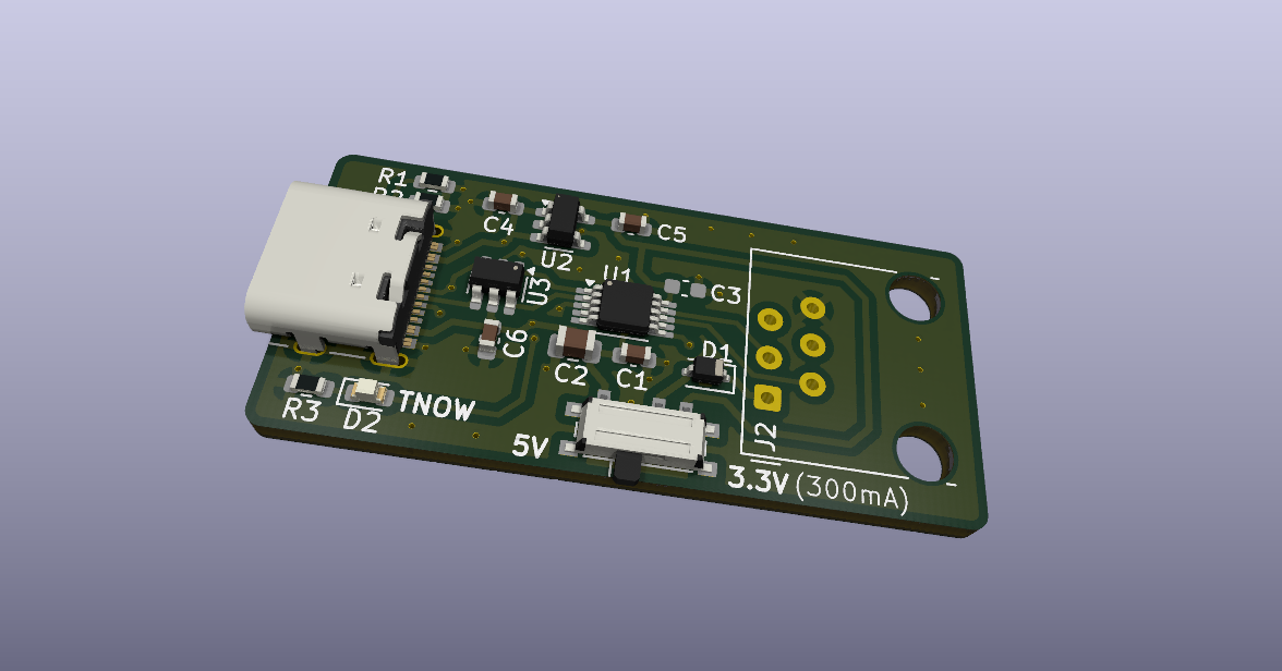
Board Layout and 3D Render
The PCB was designed in KiCad, keeping it as small and routing-efficient as possible.
Here is a 3D render of the assembled board:
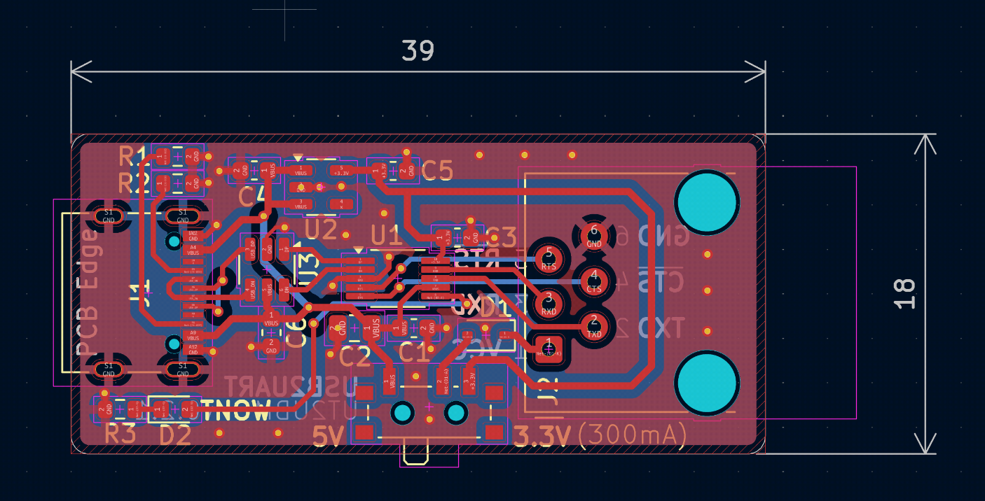
And here is the PCB layout showing the routing and component placement:
Open Source Files
This project is open-source and easy to replicate if you want to clean up your own workspace. All KiCad schematic diagrams, PCB layouts, and Gerber files are available in the project’s repository:
If you have a bunch of radios to program and want to save yourself some cable-swapping headaches, standardizing on an RJ12 interface is a highly recommended weekend project!