Standardizing the Soldering Workbench: Introducing MLight
A modern electronics workbench is a wonderful place, but it can quickly become cluttered. If you do any SMD soldering, you probably use a microscope. Along with the microscope, you need a ring light, a small external display to view your work, and a fume extractor to keep the solder smoke out of your lungs.
Each of these devices typically requires its own power adapter and cable. Before you know it, your workbench is a tangled mess of wires, and your power strip is completely full.
To solve this, I designed MLight — an all-in-one control board and custom LED ring light that streamlines power delivery, controls lighting frequency to prevent camera flicker, and drives an integrated DIY fume extractor.
In this post, I will walk you through the design challenges, features, and how the hardware and firmware come together.
The Core Features of MLight
MLight acts as a central hub for your soldering microscope setup, managing three main functions: power management, flicker-free LED control, and extraction fan speed.
1. Unified Power Management
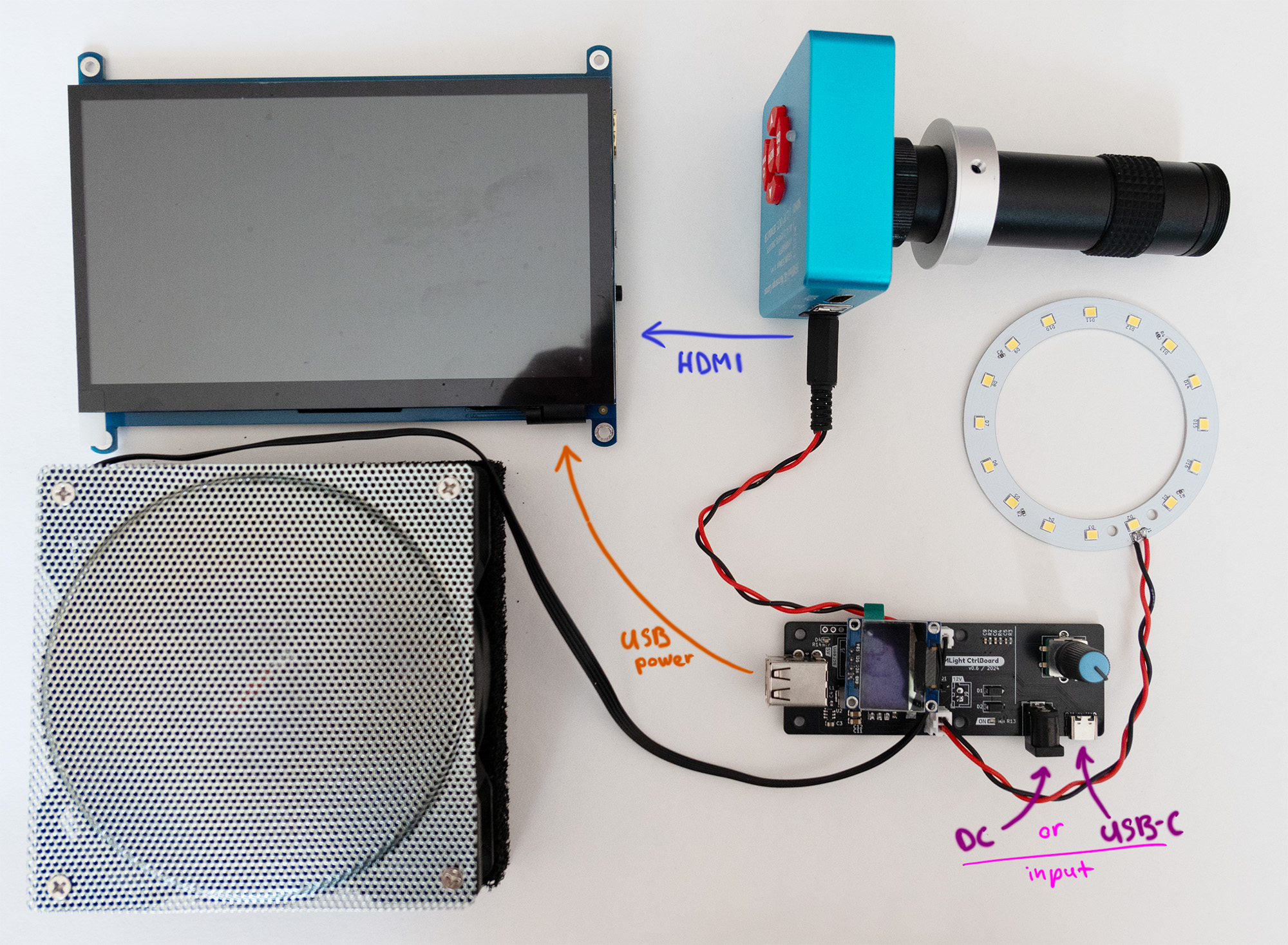
Normally, you would need power supplies for the microscope, display, and fan. MLight consolidates this by using a single input source: either a standard 12V DC barrel jack or a USB Type-C port using a Quick Charge (QC) trigger.
- The board negotiates 12V from the USB source.
- To protect the digital microscope, the power bypass output is hardware-gated and only enabled when a stable 12V input is negotiated and verified.
- An onboard AP63205 synchronous buck regulator steps down the 12V rail to 5V (delivering up to 1.5A) to power a small USB-powered external HDMI display.
2. Flicker-Free LED Brightness Control
Cheap microscope ring lights often control brightness using low-frequency Pulse Width Modulation (PWM). While this is fine for human eyes, the CMOS sensor of a digital microscope camera detects this pulsing, resulting in annoying dark rolling-shutter bands or constant screen flickering.
MLight uses a custom-designed aluminum PCB ring light with 16 high-efficiency LEDs. Crucially, the control board lets you adjust the PWM frequency on the fly to 1 kHz, 4 kHz, 8 kHz, or 16 kHz. By matching or exceeding the exposure rate of your microscope’s camera, you can eliminate rolling-shutter lines and get a perfectly clear picture.
3. Integrated DIY Fume Extractor
Solder fumes are not something you want to inhale. Instead of buying a bulky commercial fume extractor, I built a compact DIY version using:
- A high-speed, 4-pin (PWM-controlled) computer fan.
- Charcoal aquarium filters (Juwel bioCarb carbon sponges) cut to size to trap chemical particulates.
The MLight control board provides a 12V header for the fan and lets you adjust the fan’s speed percentage from the rotary encoder, keeping noise levels low when you don’t need full extraction power.
Hardware Design & Component Breakdown
Both the control board and ring light PCBs were designed in KiCad.
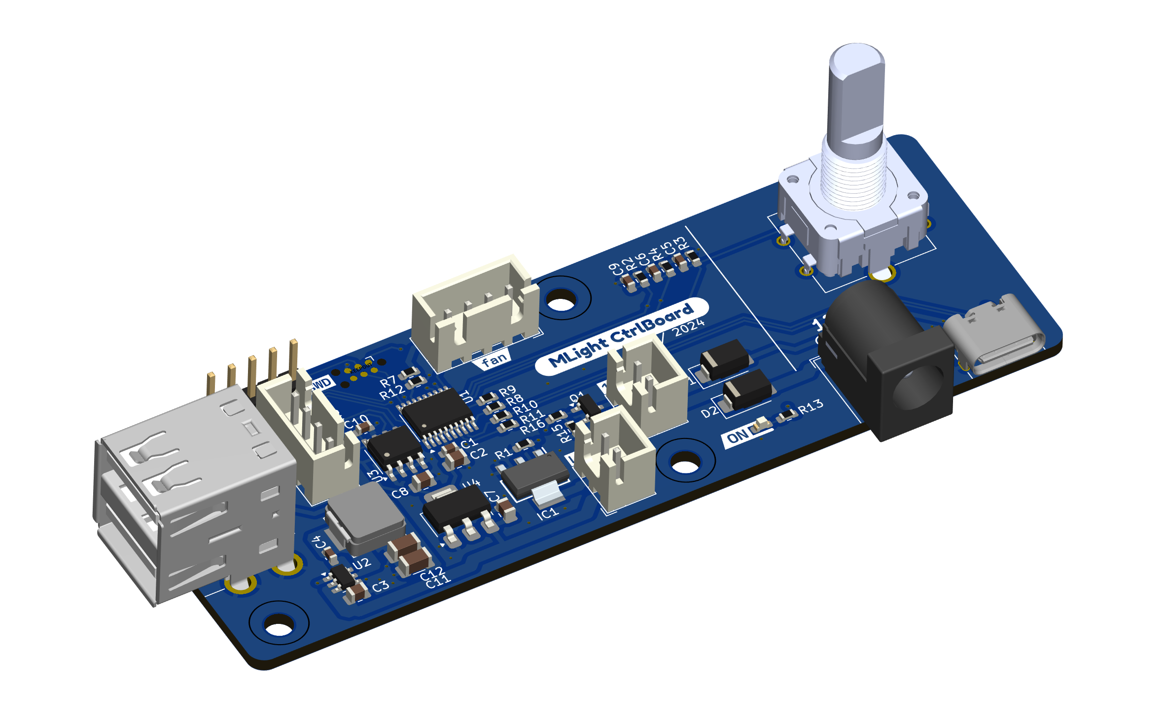
The Control Board
The brain of the board is an STM32G030F6P6 microcontroller, chosen for its low cost and built-in timers.
- AP63205: A high-efficiency buck regulator that supplies 5V for the display.
- M24C02 EEPROM: An external memory chip that stores your last-used light brightness, fan speed, and PWM frequency, so they are instantly restored when the system is powered on.
- SSD1306 OLED: A compact screen displaying real-time parameters.
- Rotary Encoder: The single input control for the device.
The Ring Light
The ring light features 16 LEDs mounted on an aluminum substrate PCB. Aluminum PCBs have excellent thermal conductivity, acting as a heatsink to keep the LEDs running cool even at maximum brightness. The bracket holds the ring light and control board neatly on standard microscope stands.
Firmware: Bare-Metal and Lightweight
The firmware was written in bare-metal C using CMSIS (Direct Register Access) in STM32CubeIDE with a CMake build system.
By avoiding heavy abstraction libraries like the STM32 HAL, the compiled binary is extremely small, and we have precise control over:
- Configuring the hardware timers for high-frequency PWM generation.
- Handling rotary encoder rotation interrupts.
- Communicating with the OLED screen and EEPROM over I2C without blocking execution.
How It Works in Practice
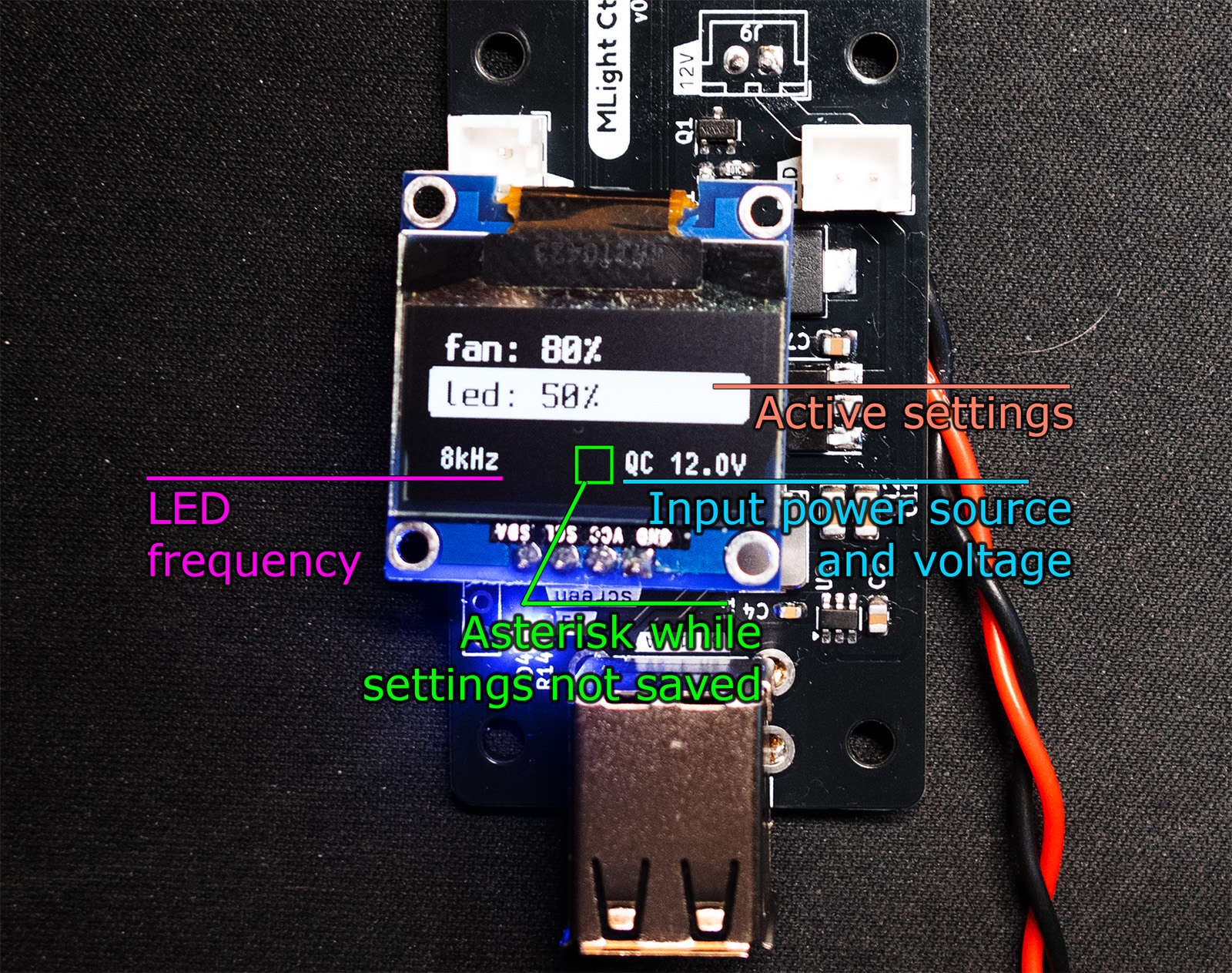
Using MLight is simple. The UI displays the active device (Light or Fan) along with its current speed/brightness and the PWM frequency:
- Short Press: Switch between adjusting the light brightness or the fan speed.
- Rotate: Tune the selected output from 0% to 100%.
- Long Press: Shut down or turn on all outputs simultaneously.
- Pressed Rotate: Cycle the light’s PWM frequency to clear up any camera artifacts.
You can watch a brief video demonstration of the controls and system in action: 👉 MLight Operation Video on YouTube Shorts
Get the Project Files
The MLight project is entirely open-source. If you want to build your own, customize the brackets, or dive into the firmware code, all files are available on GitHub:
👉 GitHub Repository: Quard/MLight
For a complete breakdown of the assembly, BOM, and schematic schematics, check out the official MLight project page.